Whiteboard Drawing Bot - Part 1
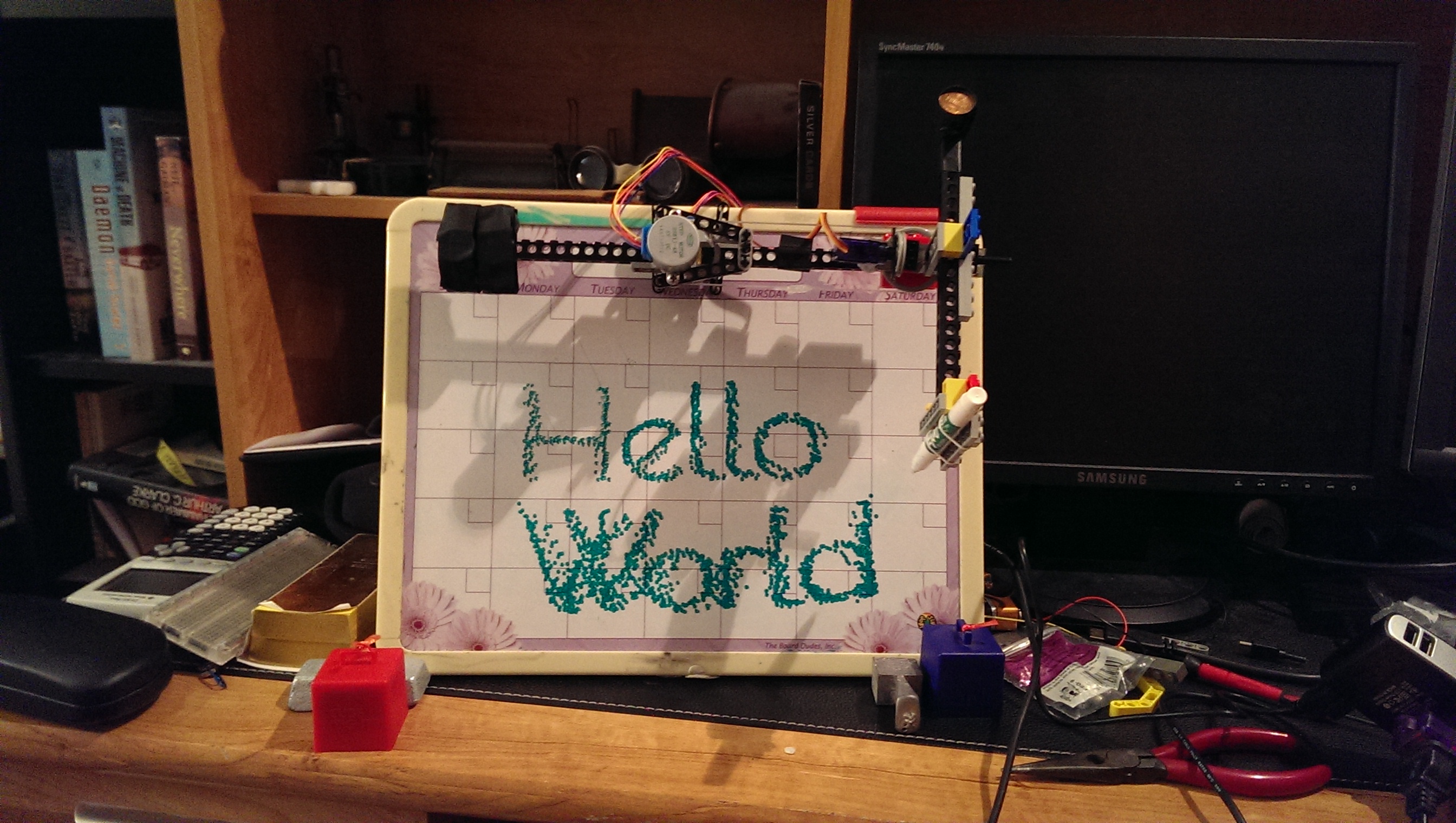
For the last couple of weeks, I have been working on creating a "whiteboard drawing bot", a Raspberry-Pi-powered contraption that can draw shapes and text on a whiteboard. After four redesigns and about a thousand lines of code, I'm finally finished. Tada!
Anyways, now that I have finished building it, I am going to write a bit about how I did so in a few posts. For this first post, I'm going to be talking about the hardware behind the bot and a little bit of the software on the Raspberry Pi. Then, later, I'll talk about the custom software I wrote to translate shapes and lines into commands for the Pi.
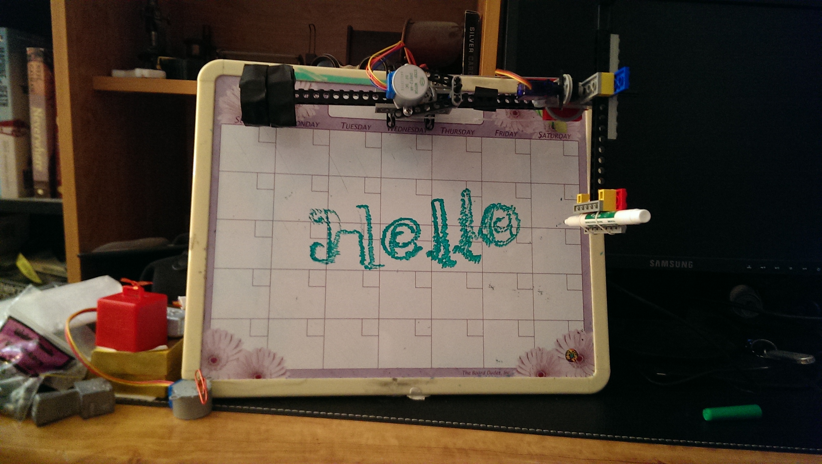 Trying out a curvier font
The Parts
In the end, I ended up using:
- a Raspberry Pi Model B
- an Adafruit Pi Cobbler with GPIO ribbon cable
- an MCP23017
- two L293D H-bridge motor drivers
- two 28BYJ-48 reduction stepper motors
- one Adafruit Micro Servo (Tower Pro SG92R)
- a USB WiFi adapter (not strictly necessary)
- 6 AA batteries
- a spare USB to MicroUSB cable
- lots of wires
- Lego Technic pieces
- a whiteboard marker
- at least 50 pennies
- some electrical tape, some thick wire, some screws, and some glue gun glue
The Design
I knew from the start that I would be using stepper motors, as their fine control would enable me to accurately position the marker on the whiteboard. The rest of the design, however, had quite a few more iterations.
My original idea was based on some other similar projects I found online. These projects essentially suspended a marker from fishing line or thread and used stepper motors at the corners of the whiteboard to move the pen along the board. I, however, wanted the pen to be able to lift off of the whiteboard, which would not be feasible with this approach. After some ideas involving a marker that rested inside a 3d-printed tube and had gear teeth glued to it that were connected to another motor that pushed the marker in and out of the tube, I decided to go with a different strategy.
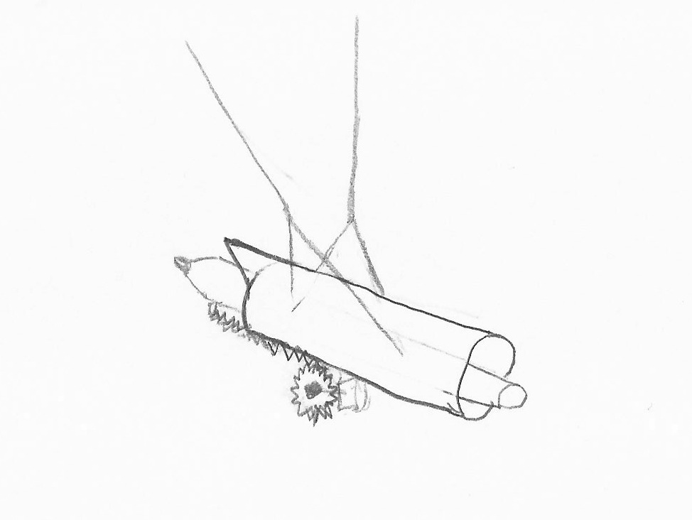
My first design.
My second idea was to use a two-part mechanical "arm" to draw on the whiteboard, with one stepper motor at the start of the first piece and one on the joint of the first and second. I was pretty sure my stepper motors would not be able to support or lift that much weight, however, so I decided to have a 3-part arm with the third part acting as a counterweight, ensuring that the motors would not be fighting gravity as they moved. To keep the two outer arms moving together, I thought of attaching them with struts that would make a parallelogram shape and thus keep the arms parallel. The difficulty in actually building this design, however, forced me to think of another method.
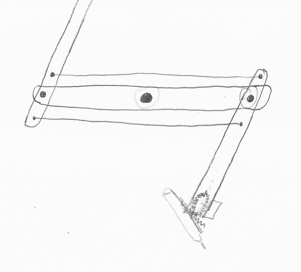
My second design idea
Eventually, I settled on using Lego gears to keep the counterweight arm parallel. The marker was raised and lowered using Lego gears and Lego Technic pieces. I assembled this design using Legos and was ready to try it out with the stepper motors. Unfortunately, I ended up breaking it down before I took a picture, but you can see some of the pieces here.

Pieces of the third design.
This design, however, had a fatal flaw: it was too massive. When I attached the stepper motor to the middle of the contraption, the motor couldn't generate enough torque to get it to spin accurately or stop at the appropriate location. (I did, however, discover that the stepper motor shaft fits perfectly inside a Lego Technic hole with enough friction to hold it in place.)
I scrapped that design and rebuilt it into my next design, which I also don't have a picture of. (It was essentially the final design but with the secondary arm attached directly to the rotating wheel.) Basically, I used much lighter pieces, and moved the two stepper motors to be right on top of each other, minimizing the rotational inertia. I then put a single arm with a counterweight on one side of the middle bar, and simply added another counterweight on the other side. Unfortunately, I still needed to figure out how to lift the pen up and down.
The final design fixes this problem by adding a servo that rotates the entire second arm piece along the axis perpendicular to the arm's orientation, effectively lifting the end of the arm up and down. In order to control the position of the second arm, I used some spare rubber tubing wrapped around two Lego wheels and kept tight with hot glue. I tried to minimize the weight of the parts in this design, and made the counterweights out of pennies (because it turns out they are actually quite cheap weights.)
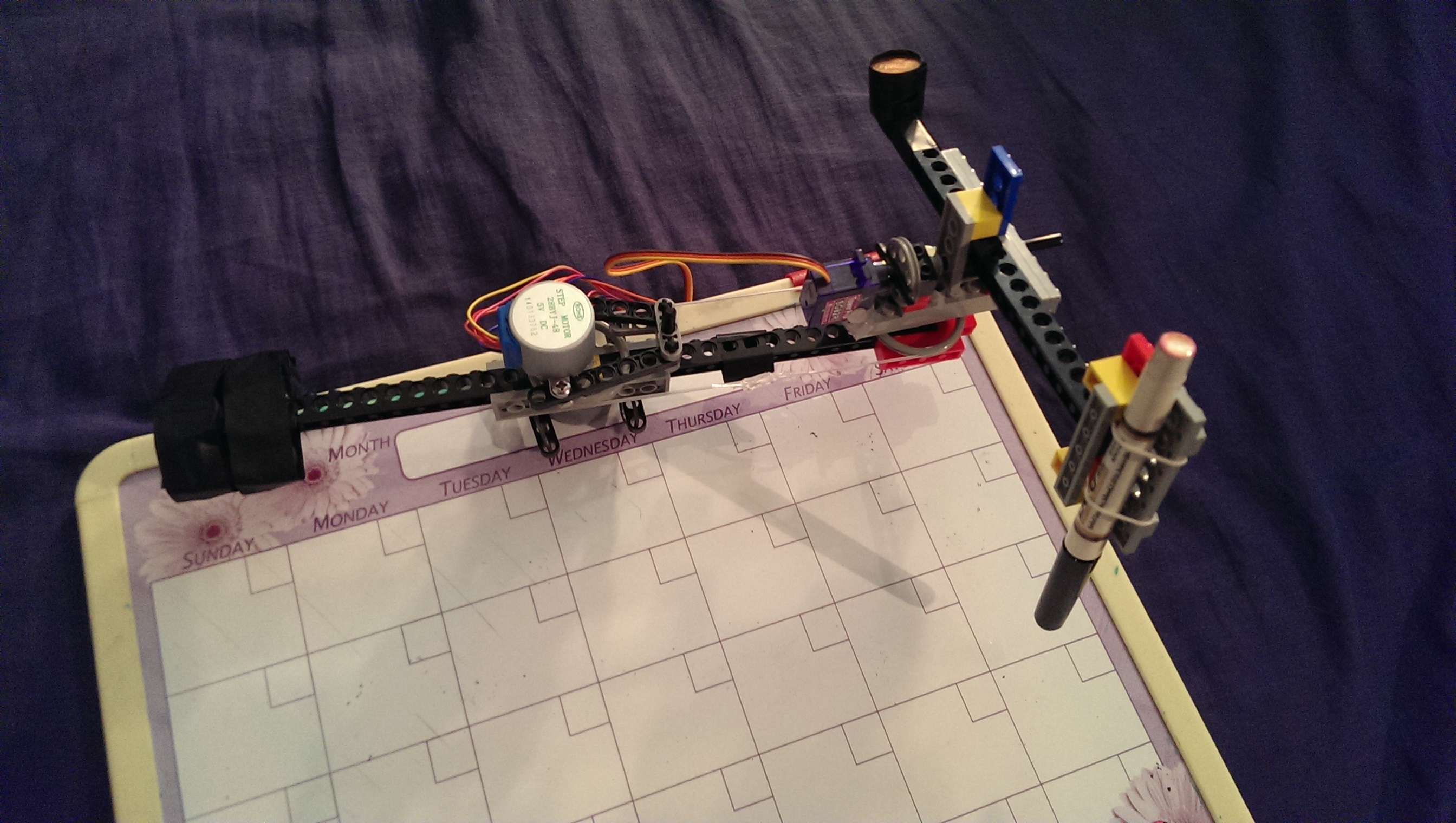
A front view of the contraption. Note the counterweights, which I made out of pennies.

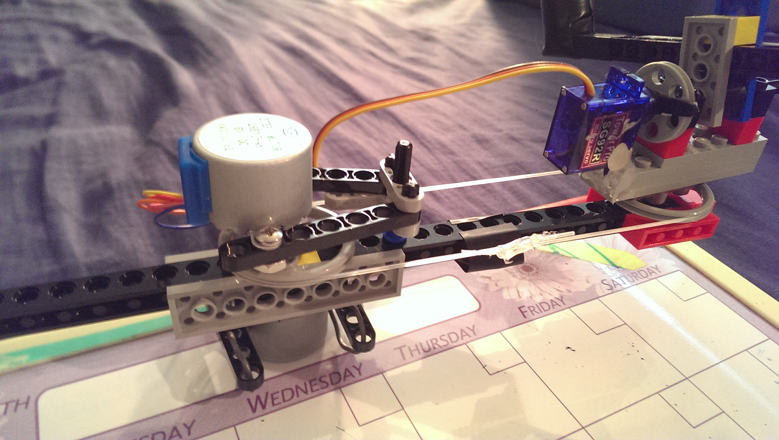
The joint between the two arms. The servo controls the pen height.
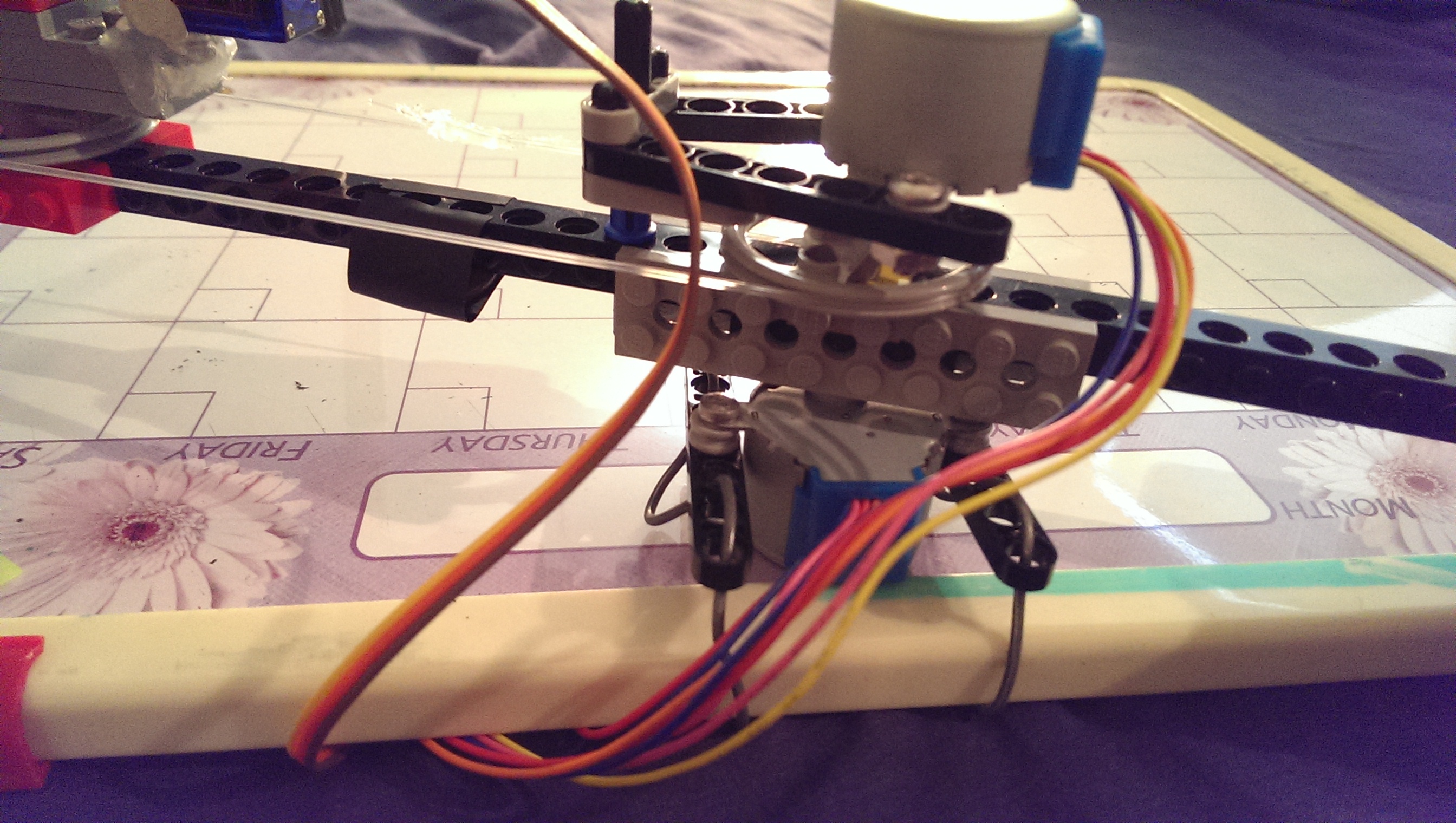
The center of the first arm. The top motor controls the second arm using the rubber tubing, and the bottom motor spins the entire thing.
 *A different view of the stepper motors.
The Electronics
Stepper motors are driven differently than other types of motors. Inside a stepper motor, there are multiple coils of wire that act as electromagnets and direct a center magnet wheel to specified orientations.
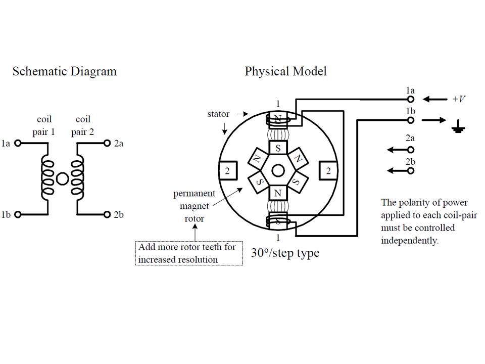
From http://homemaderobo.blogspot.com/
In order to drive a bipolar stepper motor, you must be able to direct current in either direction through the coils to change their polarity. The stepper motors also require higher voltages and more current than are supplied by a Raspberry Pi's 3.3-volt General Purpose Input/Output (GPIO) pins. To drive each of my two motors, I used a L293D motor driver. The L293D serves two purposes: It allows me to control a high-voltage output using a low-voltage, low-power input, and it allows me to switch the direction current flows through the outputs.
Unfortunately, each L293D requires 5 inputs, one for activation and one for each of the four outputs. That means that, even if I connect the two activation pins together, I still need 9 GPIO pins to control the two motors. The Raspberry Pi only has 8 GPIO pins, so I had to use a GPIO port expander. Either the 8-pin MCP23008 or the 16-pin MCP23017 would have worked, but I used the MCP23017 just to be safe. These chips are driven using I²C (which Wikipedia defines as "a multi-master, multi-slave, single-ended, serial computer bus invented by Philips Semiconductor"), allowing them to be controlled using only the two I²C pins on the Raspberry Pi.
I connected the inputs of the L293Ds to the A register of the MCP23017, and connected the activation pin to the Raspberry Pi directly. I also connected the servo control pin to GPIO 18, the dedicated PWM (Pulse-width modulation, essentially toggling an output on and off very fast with a specific on-off ratio) pin of the Raspberry Pi. This is a Fritzing sketch of the design:

The breadboard design, made with Fritzing.
The actual wiring ended up being slightly different than this. I decided to power the servo using the 5v power from a spare USB charging cable that I cut up, connecting wires to the red and black leads of the cable. I found that 5v was not enough to make the motors control the arm smoothly, so I connected 6 AA batteries to them to provide 9 volts. (The motors have 5v written on them, but they are identical in appearance and cost to the manufacturer's 12v motors with the same part number, so I had a hunch that anything between 5 and 12 volts would work.)
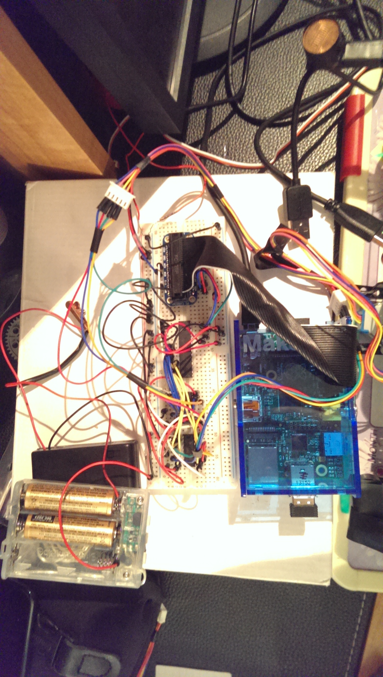 Lots of wires! Wires everywhere!
I loaded my Raspberry Pi with Adafruit's Occidentalis 0.2 distro because it had patches that allow it to easily drive PWM and connect to I²C devices. The code running on the Pi that controls the motors is written in Python, and interfaces with Adafruit's MCP230XX library for controlling the MCP23017. I configured my Pi to use ssh and ssh-ed in from my Macbook to upload the code and configure everything. To send drawing commands to the Pi, I used Node.js to make a simple server. (I probably could have used Python for that, but I'm more familiar with Node. Also, the command-generating software I wrote runs in Javascript, so it made sense at the time.) Node.js and Python communicate with each other using a Unix domain socket, which is essentially a "file" that can be opened by multiple processes and that enables communication between them just like a web socket would. If you are curious about the code, I put it all in a GitHub repository.
If you are interested in the code used to generate the commands, you can continue reading with Part 2.